Sony Str De475 User Manual Pdf
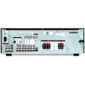
My receiver is a Sony STR-DE475, which has no phono inputs. The internet seems to indicate that I need some type of phono preamp- but I've got this working in the past without one. However, no matter how much manual-reading and messing around I do, I just can't get it to work again. About This Manual The instructions in this manual are for models STR-DE475 and STR-K402. Check your model number by looking at the lower right corner of the front panel. About area codes The area code of the player you purchased is shown on the lower portion of the rear panel (see the illustration below). Manual Library / Sony. Sony STR-DE475. Audio Video Receiver (2001) add a review. Username or e-mail:. Password. This website is not affiliated with or sponsored by Sony. To purchase STR-DE475 spares or accessories, please contact the company via their website or visit an authorised retailer.
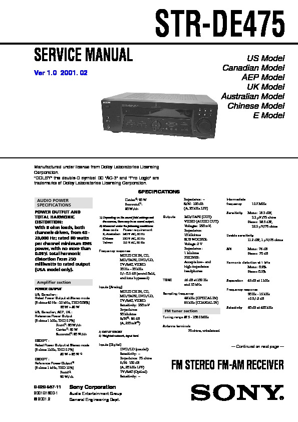
Read Sony STR-DE475 Service Manual online

SONY STR-DE675. View 37 Best sony str de475 images. Sony Str De475 User Manual Sony Str De475. User Manual Sony Str De475. Source Abuse Report. Sony Str De475. Num.1 Search Engine: owner's manual, instructions book, user's guide, service manual,schematics, illustrated parts SONY STR-DE675 User's Guide French SONY STR-V1. Brand Name: sony Can I get a Hardcopy / Printed Version of the manual? Our printing service is the best on the web in Product Quality & Speed of shipping!
Sony Str K502p Review
Corporation.
“DOLBY” the double-D symbol
VIDEO (AUDIO OUT):
Voltages: 250 mV,
Impedance:
10 kilohms
SUB WOOFER:
Voltage: 2 V
Impedance :
1 kilohms
PHONES:
Accepts low– and
high-impedance
headphones
and 10 kHz
96 kHz (COAXIAL IN)
Stereo: 70 dB
Stereo: 0.5%
+0.5/-2 dB
TOTAL HARMONIC
DISTORTION:
With 8 ohm loads, both
channels driven, from 40 -
20,000 Hz; rated 80 watts
per channel minimum RMS
power, with no more than
0.09% total harmonic
distortion from 250
milliwatts to rated output
(USA model only).
Reference Power Output

Chinese
MD/TAPE, DVD/LD,
TV/SAT, VIDEO:
20 Hz – 20 kHz
0/– 0.5 dB (sound field,
and tone bypassed)
MD/TAPE, DVD/LD,
TV/SAT, VIDEO:
Sensitivity: 250 mV
Impedance:
50 kilohms
S/N
4) Weighted network, input level
Sensitivity: –
Impedance: 75 ohms
S/N: 100 dB
(A, 20 kHz LPF)
TV/SAT (Optical):
Sensitivity: –
530 - 1710 kHz
530-1610 kHz
TUNING + button and press the
button. All preset stations will be erased
when you change the tuning scale. To reset
the scale to 10 kHz (or 9 kHz), repeat the
procedure.

220 -230 V AC,
50/60 Hz
In Standby
Condition:
1 W
In Standby
Condition:
1 W
In Standby
Condition:
1 W
In Standby
Condition: 1 W
to change without notice.
• AM loop antenna (1)
• R6 (size-AA) batteries (2)
• Remote Commander (remote) (1)
COMPONENTS WITH SONY PARTS WHOSE PART NUMBERS
APPEAR AS SHOWN IN THIS MANUAL OR IN SUPPLEMENTS
PUBLISHED BY SONY.
following safety checks before releasing the set to the customer:
Check the antenna terminals, metal trim, “metallized” knobs, screws,
and all other exposed metal parts for AC leakage. Check leakage as
described below.
from all exposed metal parts to any exposed metal part having a
return to chassis, must not exceed 0.5 mA (500 microamperes).
Leakage current can be measured by any one of three methods.
WT-540A. Follow the manufacturers’ instructions to use these
instruments.
digital multimeter is suitable for this job.
VOM or battery-operated AC voltmeter. The “limit” indication
is 0.75 V, so analog meters must have an accurate low-voltage
scale. The Simpson 250 and Sanwa SH-63Trd are examples of
a passive VOM that is suitable. Nearly all battery operated
digital multimeters that have a 2V AC range are suitable. (See
Fig. A)
Voltmeter
(0.75 V)
Sony Str De425 Manual
CRITIQUES POUR LA SÉCURITÉ DE FONCTIONNEMENT. NE
REMPLACER CES COMPOSANTS QUE PAR DES PIÈSES SONY
DONT LES NUMÉROS SONT DONNÉS DANS CE MANUEL OU
DANS LES SUPPÉMENTS PUBLIÉS PAR SONY.
3-11. Printed Wiring Board Display Section ····················· 18
3-12. Schematic Diagram Video Section ·························· 19
3-13. Printed Wiring Board Power Section ······················· 20
3-14. Printed Wiring Board Video Section ························ 20
3-15. IC Block Diagrams ····················································· 21
3-16. IC Pin Function Description ······································ 23
| Recognized languages: | English |
|---|---|
| Pages: | 1 |
| Size: | 64 KB |
| Recognized languages: | English |
|---|---|
| Pages: | 22 |
| Size: | 228 KB |
- FM Stereo FM'AM Receiver
- WARNING
- Precautions
- About This Manual
- Hookup Overview
- Inserting batteries into the remote
- Antenna Hookups
- Overview
- Hookups
- Connecting a ground wire
- Audio Component Hookups
- Hookups
- Speaker System Hookups
- Overview
- Hookups
- Video Component Hookups
- Hookups
- AC Hookups
- Selecting a Component
- Using the remote
- Changing the factory setting of a function button LlI
- Receiving Broadcasts
- Presetting Radio Stations
- Tuning preset stations (preset tuning)
- Recording
- Recording on a video tape
- Using the Sleep Timer
- Choosing a Surround Mode
- Adjusting the Effect Level (for C. STUDIO and HALL only)
- Getting the Most Out of Dolby Pro Logic Surround Sound
- Adjusting the delay time
- Troubleshooting
- Specifications
- Glossary
| Recognized languages: | English |
|---|---|
| Pages: | 2 |
| Size: | 19 KB |